Mullet Hall – Thermal Bridge Mitigation at Slab

All too often, I am approached towards the end of the design phase of a project and asked to create an overlay scheme for energy efficiency. One of the major drawbacks of this approach is that an approach to mitigating thermal bridges must be developed very early on in a project.
Just as a suspension bridge creates an easy pathway over a body of water, a thermal bridge creates an easy pathway for heat transfer through a building envelope.
There is a broad understanding in the construction industry and in the general public of the importance of insulation, and there seems to be a fairly wide understanding of the concept of “R-value.” When designing a high performance building, it is critical to broaden the focus from insulation R-value to include both air tightness (which I will address in a future post) and thermal bridging.
Most wall R-value insulation listings (as you would see on the outside of a package of insulation at a big box store) is providing a center of wall insulation value.
At Mullet Hall (formerly referred to as 1 Brave Scout Trial), we have incorporated a variety of strategies to mitigate thermal bridging, as I discussed in this previous post.
Column bases

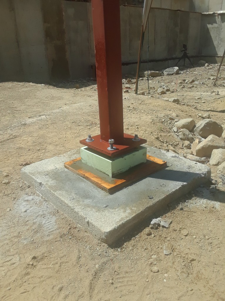
A major conductor of heat – and therefore a major thermal bridge – is any metal penetration through the building envelope. To mitigate thermal bridging through the steel columns into the main living space (and the garage), we placed the steel columns on Armatherm bases.
Foundation/slab transition
A major point of thermal bridging comes at building component transitions: foundation/wall; first floor/second floor; wall/roof, etc.
In all of these transitions, it is common for there to be a sill plate or other bearing plane that creates a continuous joint which conventionally is uninsulated and therefore a major thermal bridge. At all of these transitions, our strategy is to attempt to overinsulate – in other words, we insulate over the thermal bridge to mitigate its effects.
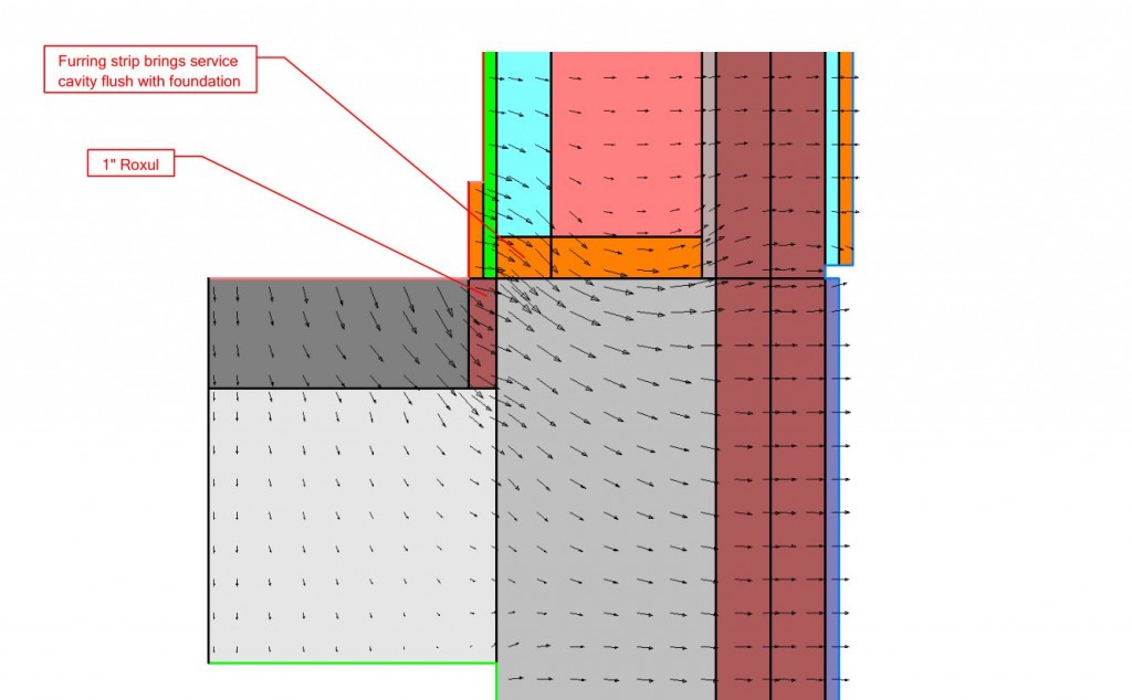
At the foundation/wall transition, we planned the wall section to allow for the foundation insulation to be continuous with the wall insulation above, as seen in this THERM model.

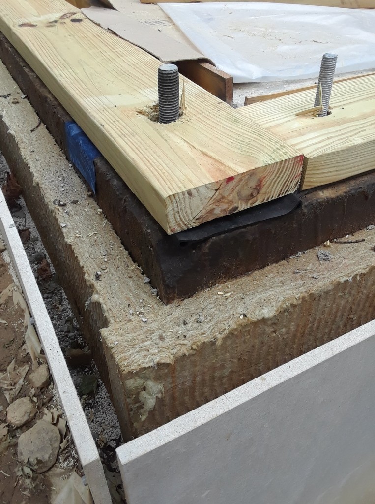
This drawing translated into reality, wherein you will see the 4″ of continuous Rockwool insulation continuously running from the foundation perimeter to the framing.

In the image above, you can see the 4″ of Rockwool insulation at the foundation wall, and the sill plate located in such a way that this insulation can extend in a continuous plane up over the framed wall. This mitigates the thermal bridge at the sill plate. In addition, you can see in the THERM model detail that the slab on grade is held off of the foundation wall – with the space created by a strip of lumber, then pulled out and replaced with a strip of Rockwool. This mitigates the thermal bridging between the foundation wall and the slab.

